Hydraulic Clutch System Diagram
Hydraulic clutch system diagram. In service the main problems that will be encountered are likely to. Toyotas New Six-Speed Automatic Transmission A761E for RWD Vehicles Figure 9 shows the hydraulic circuit diagram for the C3 clutch and B2 brake. We also have a video Ranger Bleeding Part 2 httpwwwyout.
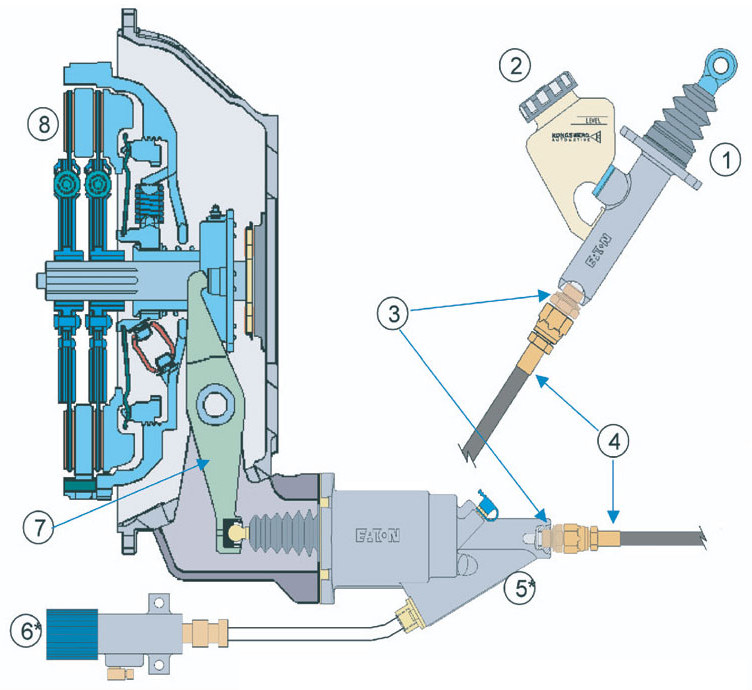
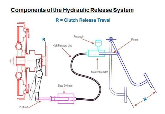
In the diagram below we can see the main components of a hydraulic clutch actuation system. A cutaway diagram shows both the physical arrangement and the operation of the different components. If you arent comfortable with the point at which your clutch engages you can easily adjust it by following the steps below.
Headlamp Parking Lamp Taillamps. There are two conical surfaces for transmitting torque by friction. A comparative consideration can also be made with the frictions in the entire system.
Video shows an easy way to bleed the clutch hydraulics on a Ford Ranger or Mazda B-Series pickup. The system works similar to how the brakes work on your vehicle. It is generally used for instructional purposes because it explains the functions while showing how the system is arranged.
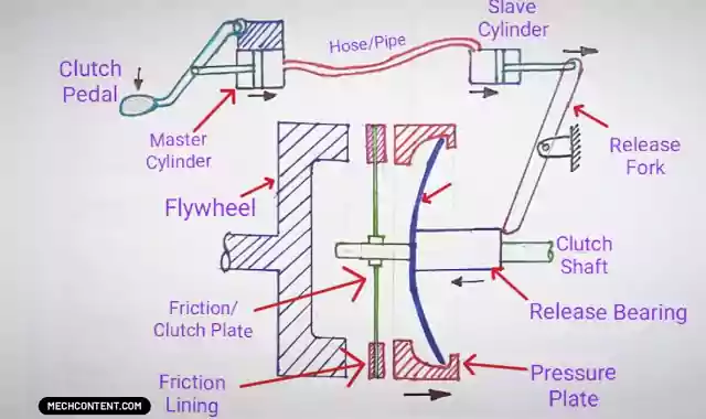
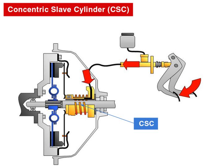
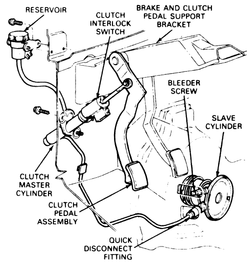
System Components and Operation Hydraulic Components and System Operation The hydraulic clutch system consists of a hydraulic reservoir master cylinder hydraulic hose slave cylinder and clutch pedal. The advantage of Hydraulic Clutch is Less Effort is required to Press the Clutch Pedal. Clutch systems with reduced forces offer potential in assembly standardization in the area of clutch and release systems with lower release system ratios.
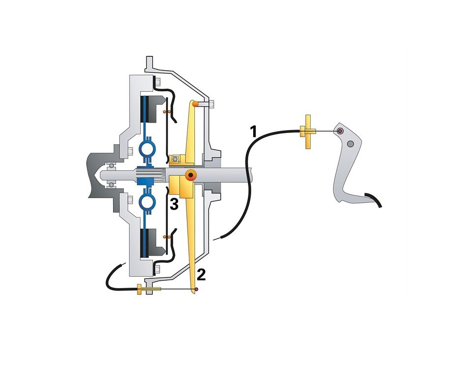
2 Oil flows from the master cylinder to cylinder 2 through a pipeline. Leave the adjustment bolts on the Outer Mounting Bracket finger tight so the angle of the Master Cylinder can be adjusted later. The standard fluid should be maintained in the hydraulic systems.
Group 41 Hydraulically Actuated Clutch Clutch and Hydraulic Clutch System Volvo Clutch Plates The Volvo clutch plates are dry with linings on both sides. Most clutches especially on older vehicles work by means of a cog system that changes the gears as you shift.
2 Oil flows from the master cylinder to cylinder 2 through a pipeline.
The disc is connected to the hub by friction elements and damper springs to provide a smooth. Install the Reservoir or Reservoir Nipple on the Master Cylinder body. Citroën D Models - Hydraulic Course Notes. Hydraulic Clutch is one of the Type of Automobile Clutch. Toyotas New Six-Speed Automatic Transmission A761E for RWD Vehicles Figure 9 shows the hydraulic circuit diagram for the C3 clutch and B2 brake. The pipe can break or teared down. If your car transmission has a hydraulic clutch chances are youre wondering exactly how it works within your shifting system. When the clutch pedal is depressed fluid from the master cylinder forces the slave cylinder to move the clutch release fork. It is operated with the application of pressure by the lever through a piston in the master cylinder which then transfers the force to the slave cylinder.
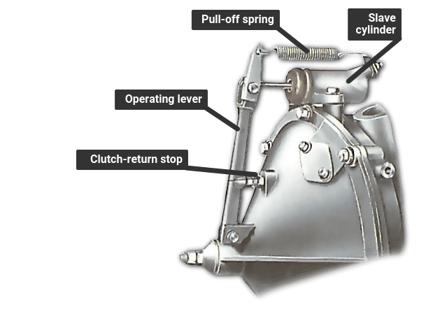
In this Type of Clutch Fluid is used to Operate the Clutch. A hydraulic clutch system works using various hydraulic components to actuate the clutch when the pedal is pushed in. System Components and Operation Hydraulic Components and System Operation The hydraulic clutch system consists of a hydraulic reservoir master cylinder hydraulic hose slave cylinder and clutch pedal. Transmission Regulated Spark System. When the clutch pedal is depressed fluid from the master cylinder forces the slave cylinder to move the clutch release fork. The hydraulic clutch works similarly to the brake systems on modern motorcycles. We also have a video Ranger Bleeding Part 2 httpwwwyout.















A typical underground dog fence system comprises checkout this page several key components: the transmitter, boundary wire, and receiver collar.
ReplyDelete